Standard User Interface Drawings
This is a work in progress and is presented to encourage discussion
and refinement in order to document a standard solution.
Please contact us with your comments
Introduction
This page is a collection of drawings and wiring diagrams for the
Standard User Interface
Prototype Drawings
The Standard User Interface defines the connections and wiring, but
does not specify the cabinet in which to build the interface. The
purpose of the interface is to establish a standard capability and the
wiring to support that capability.
Front View
The front view shows the jacks, switches, volume controls and indicator
lights that would be included in the user interface.
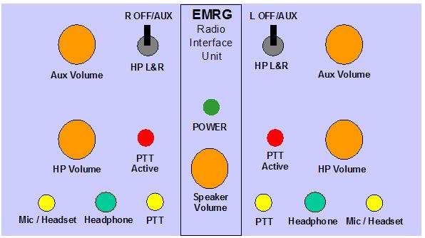
- LED Indicators
- Power - Indicates that the User
Interface has 12 VDC power from the standard interface connector.
PTT Active - Indicates when PTT is active and which operator has
activated it.
- Headphone
- Headphone jacks are 3.5mm (1/8") stereo
phone plugs. This is will accept any of the headsets made for stereos
today as well as many of the commercial radio headsets.
- Microphone / Headset
- The Microphone / Headset jacks are 2.5mm
(3/32") stereo phone plugs. This is only an idea at this time, but this
is the same jack used in most cordless phones and cell phones. There
are many commercial headsets available, that are wired with the plug
for this jack. The idea is to use this for any microphone inputs, by
providing microphone bias voltage at the jack, while also providing a mono
headset connection.
- PTT
- The PTT jack is a 2.5mm (3/32) mono
phone plug. This can be used to plug in a hand switch or for headsets
that have a built in PTT switch. There is a second PTT jack on the back
of the user interface to plug in a foot switch, so the users can have
the option to make it easier during extended periods of operation.
- HP Volume
- Each user has their own headphone volume control
- HP L and R Switch
- Each user has a switch that will
disable one side of there headset, to make it easier to converse with
the person next to them. The left users switch turns off the right side
of their headset, while the right user's switch turns off the left side
of their headset. The other position for the switch will turn off one
side of the headset and connect it to the auxiliary. input from the back of
the unit. This allows a second radio or scanner to be connected to the
auxiliary input, so the operators can listen to 2 radios at once.
- Auxiliary Volume
- Each user can adjust the auxiliary input volume for their headset.
- Speaker Volume
- The speaker volume controls the output
of the speaker jack on the back of the user interface box. If there is
a message on the radio that someone needs to hear, the operators can
turn up the speaker. The speaker could also be on an extension, so the
group being supported can listen to the radio.
Back View
The back of the user interface box has the connections that are not
required on the front of the box.
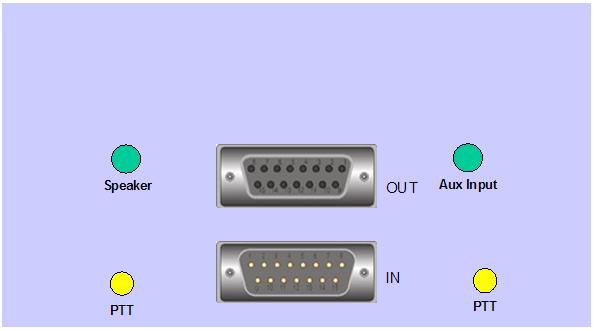
- IN
- The DA15 IN connector plugs into the
Standard Radio Interface. The User Interface could be beside the radio,
or extended up to several hundred feet using an extension cable. The IN
connector provides all the radio interface signals as well as 12VDC.
- OUT
- The DA15 OUT connector is wired to the
IN connector. The OUT connector allows a second user interface to be
extended for the same radio. The extra user interface may be at the
other end of the same table, or could be on the other side of the room.
- PTT
- The PTT jack is a 2.5mm (3/32) mono phone plug. This can be used to
plug in a foot switch. There is a second PTT jack on the back of the
user interface to plug in a hand switch or for headsets that have a
built in PTT switch, so the users can have the option to make it easier
during extended periods of operation.
- Speaker
- The Speaker jack is a 3.5mm (1/8") mono
phone plug. This allows an external speaker to be plugged in, without
the users having to unplug headsets. The speaker could be located
beside the users for occasional listening or could be extended along
the table or to another part of the room to allow other participants to
listen.
- auxiliary Input
- The auxiliary Input jack is a 3.5mm (1/8")
mono phone plug (another option is RCA). This allows a second receiver
to be connected to one side of the users headset. The extra radio could
be an FRS radio, scanner or another amateur radio. If it is an amateur
radio with the standard interface, then an adapter is required.
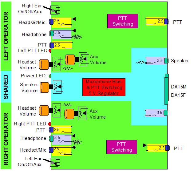
Internal View
The internal view shows a sort of top side, looking into the box view.
The User Interface will require a few innovative wiring techniques.
Many of these ideas are from the CAIRO documentation. The UK group did
a lot of thinking when they developed their system.
- Headphone
- There is a resistor in line with the
headphone jack to limit the signal level. The jack on the back of
the radio is for an external speaker and headphones connected directly
to that can provide signal levels that hurt hearing. The resistor is a
safety feature to limit the signal level.
- Headset Volume
- There is a resistor in line with the
headset volume, so the user cannot turn the volume all the way down.
Even with the volume control turned all the way down, there will still
be some signal in the headset.
- PTT
- PTT switching will be required to
activate the correct microphone and PTT LED indicator. This will ensure
that the other operators microphone is only on if that operator pushes
the PTT. This avoids a problem of having both microphones on, when one
operator is activating PTT, and the other operator is having a
conversation with someone.
- Speaker
- The speaker jack is a switching type,
so there is an 8 ohm resistor across the terminals when no speaker is
connected. Plugging in a speaker, will bypass the resistor. This is an
idea that has not been tested, but the concept is that this may limit
signal level changes for other users when a speaker is added or removed
from the system.
- Microphone Bias
- Most microphones require a low level
microphone bias voltage. The voltage will be supplied using the
auxiliary 12VDC from the Standard Radio Interface, with a voltage
regulator.
Extension Cables
One of the big advantages of implementing the Standard Radio Interface
and the Standard User Interface, is the ability to use an extension
cable to locate the user up to several hundred feet from the radio. The
extension cable will be smaller and more flexible than coax and the
several hundred feet does not impact the final output from the radio.
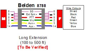
Exceptionally long cables require individual shielding of signal
cables. Belden makes a 5 wire cable with 3 wires individually shielded.
For the end user application, 5 wires is sufficient. Here is a sample
extension cable.
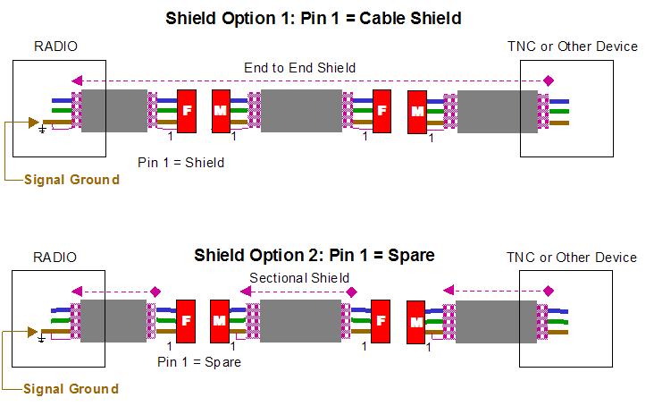
There are some issues with extension cables, regarding how the shielding
is handled. Option 1 uses pin 1 to connect the shield between each
section, making an end to end cable shielding. Option 2 attaches the
shield to signal ground, freeing up pin 1 for other purposes.