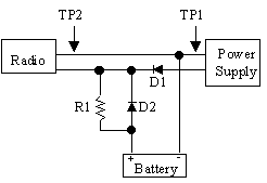
Figure 1 Power Supply Charging Circuit
The "gel cell" is often used for back up or remote power of radios and other amateur equipment. In most cases, the intentions are good, but the ongoing maintenance or lack there of, leads to disappointment due to short operation times or premature failure of the battery.
There are chargers available that will maintain the gel cell at optimal level ready for use, as well as ensure proper charging currents to minimize charge time but not damage the battery. The cost for these chargers exceeds the price of the gel cells, so ad hoc methods are used to keep the battery charged. This article provides one method of charging and maintaining gel cell batteries to ensure peak performance and long life.
Gel cell batteries that are being charged for backup or emergency use, should be connected to a charger that will maintain them at a "float" voltage at all times. The typical float voltage is 13.4 to 14.1 volts. If the voltage is maintained within this range, the battery can be left connected to the charger, without damage. This ensures that the battery is at peak performance at all times.
It is possible to use a standard 13.8V DC power supply to charge and maintain your 12 volt gel cell battery. There are some limitations in using this method, but there are also some good reasons to use it.
The typical radio power supply is regulated for 13.8 volts DC. This is about the same as the float voltage for a gel cell battery. In theory, you could connect the battery to the power supply for charging. This is not a good idea and is dangerous. The problem is that there is no way to control or limit the charging current. If your battery was significantly discharged, the initial charge current would be high and the battery could be destroyed or damaged.
The current can be controlled, by inserting a current limiting resistor (R1 in Figure 1) between the battery and the power supply. This will limit the initial charging current to a safe level. However as the battery charges, its voltage increases, while the voltage across the resistor decreases. The decreasing voltage across the resistor reduces the charging current, increasing the charging time.
The resistor alone will safely charge the battery, but including two diodes adds two important features;
Figure 1 Power Supply Charging Circuit
Diode D1 provides the anti back feed protection, so the power supply will not drain the battery if the AC power fails or the power supply is turned off. The second diode, D2, allows the battery to power the radio when the power supply goes off. Without the diode D2, the radio would draw its current through the current limiting resistor. The voltage drop across the resistor would be significant and would vary depending on whether the radio was receiving or transmitting. In fact, receive operation may be possible, but the voltage drop across the resistor would be too high for most radios to support transmission. Adding diode D2 solves this problem. When the power supply is operating, D1 is reverse biased so all current flows through the resistor. When the battery is powering the radio, diode D2 is forward biased and the current flows through the diode.
There are two downsides to adding the diodes, based on the fact that there is a voltage drop across the diode of 0.7 volts. The impact of the voltage drop is;
When the battery is powering the radio, there will be 0.7 volts dropped across D2, so the voltage at the radio will be 0.7 volts less than the voltage at the battery. If the battery is at best 12.9 volts when the charger fails, then the voltage at the radio is only 12.2 volts to start with and it will go down from there.
Voltage drop across D2 can be overcome by installing a switch or relay, which simultaneously bypasses diode D2 while removing the power supply connection from D1. The switch and relay provide identical functions, but the relay will do the switching automatically, while with the switch there is always the possibility of someone forgetting to set the switch back when the AC power returns.
Figure 2A shows the circuit from Figure 1, with the addition of S1, a SPDT switch. When the switch is in the position shown in the diagram, the battery is connected directly to the radio, bypassing diode D2, eliminating the 0.7 V drop across D2. The power supply connection at D1 is broken so there is no possibility of accidentally having the battery connected directly to the power supply. When the switch toggles, the power supply connection at D2 is reconnected and the bypass around D2 is removed.
Figure 2B shows the same circuit from Figure 1, with the addition of K1, a SPDT relay. The drawing shows the connection for the relays normal (non powered) state. When the power supply is applying power, relay K1 is energized, pulling the contact up so the radio is connected to D1. When the power fails, the relay contact goes back to the normal position, bypassing D2 and removing the connection at D1.
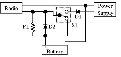
Figure 2A: Switch Bypass
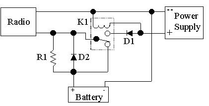
Figure 2B: Relay Bypass
There are two options for packaging this solution; install the components in a mini box or install them inside the power supply. For me, the more idiot proof the better, so I installed the resistor and diodes inside the power supply case and added an extra set of binding posts for the battery connection. You could use a wire and connector instead of the binding posts, to connect the battery. MAKE SURE YOU LABEL THE NEW CONNECTION.
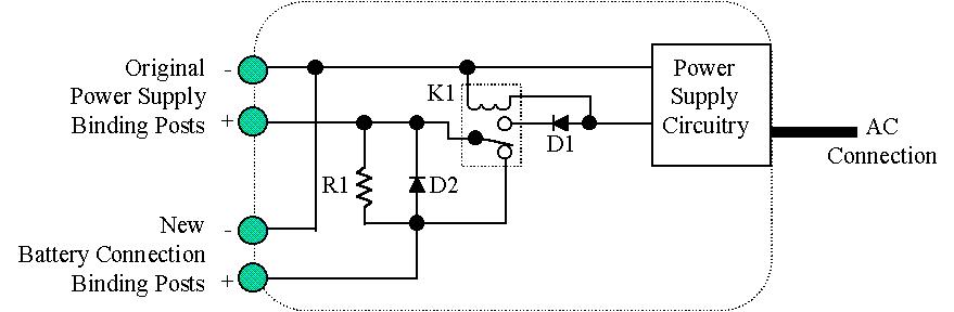
Figure 3 Modified Power Supply
The wire that attaches to the original positive binding post is cut and the diodes and resistor are added. A new wire is added from the original negative binding post, to the new battery connection negative binding post.
When the power supply voltage is increased to compensate for the diode (D1), the voltage at the original power supply output is still 13.8 VDC and there is the option to attach a battery.
If the components are installed in a mini box, which then connects to the output of the power supply, the power supply output will be 14.5 volts, which is higher than the normal 13.8 volts. It is possible for someone who doesn't know this to connect directly to the power supply instead of the adapter, which may accidentally cause damage to equipment.
Diodes D1 and D2 must have sufficient current rating to supply the requirements of the load. If the load is a mobile radio which draws 9 amps on full output, the diodes should be rated 1.5 to 2 times the required value, which would be about 15 to 20 amps for continuous service.
Half of a bridge rectifier can be used instead of two diodes. This configuration usually can be bolted to the case to dissipate heat and the tabs provide a mounting point for the resistor.
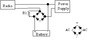
Figure 4 Circuit Using Bridge Rectifier
The resistor has two considerations; resistance and wattage. The resistance must ensure that when the battery is at its lowest voltage, which is maximum voltage across the resistor, the current flow does not exceed the battery charging rating. The wattage must be sufficient that if the battery were shorted, the resistor would support the maximum current through the resistor.
The maximum charging current is equal to CA, where C is the batteries rated capacity and A is the initial current rating from the battery manufacturer. The recommended maximum charging currents for gel cells are:
4 Ah = 0.3 x 4 = 0.12A (120mA)
7 Ah = 0.3 x 7 = 0.21A (210mA)
R = E/I, where E is the expected maximum voltage drop across the resistor and I is the maximum charging current. The maximum voltage drop across the resistor is the power supply output minus the lowest possible battery voltage. Since the battery should not be discharged below 10.5 volts, we assume a low voltage of 10 volts and a power supply output maximum of 14 volts. Therefore the maximum voltage across the resistor would be 4 volts. The resistor calculation for a 7 Ah battery would be;
R = 4 V / 210 mA = 19 ohms.
The worst case for the resistor is if the battery is shorted so that the full power supply output is across the resistor.
P = E2/R, where E is the maximum power supply voltage of 14 volts and R is the calculated resistance of 19 ohms. Therefore the minimum resistor wattage rating is;
(14 x 14)/19 = 10.5 watts.
The actual resistor wattage rating should be 1.5 to 2 times the calculated value.
The contacts should be rated at least 1.5 times the power supply current rating. For example, a 3 amp power supply would require a switch or relay with at least 4.5 Amp contact rating. Higher contact ratings are OK.
Relay K1 should be as small as possible, with a 12VDC coil.
For the typical 4Ah and 7Ah gel cells, use the three twenties;
Resistor: R = 20 ohms and P = 20 Watts
Diodes: I = 20 Amps